

02 Audi A4 Rev Lights Keyless Entry Windows and Sun Roof Not Working Fuse Is Good Free Updated
02 Audi A4 Rev Lights Keyless Entry Windows and Sun Roof Not Working Fuse Is Good Free Updated
Audi A4 (B8) is the 4th generation of the Audi A4 . Released in 2007, 2008, 2009, 2010, 2011, 2012, 2013, 2014 and 2022. This publication provides a clarification of the fuses and relays of the audi a4 b8 with diagrams and photographs of the boxes, likewise as their locations. Let's highlight the fuse responsible for the cigarette lighter.

Contents
- one Location
- two Passenger compartment
- 2.one Left dashboard fuse box
- 2.two Right dashboard fuse board
- two.3 Boosted box
- two.3.1 six-pin rack-mount connection box
- 2.iii.two Relay and fuse box with used on-board network
- 3 Engine compartment
- 3.one Box in the middle of the plenum chamber
- iii.two Switchgear fuse lath
- 4 Luggage compartment
- 5 Additional Information
Location
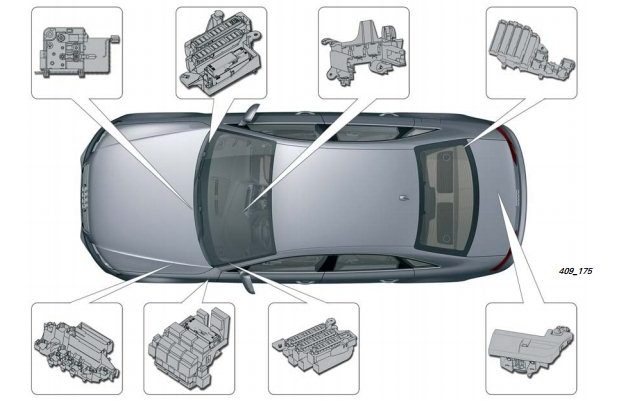
Passenger compartment
Left dashboard fuse box
To access the fuses, open the door and remove the embrace. It will look something like this. An example of access is in our video at the end of the article.

Diagram

Designation for cars audi a4 b8 before 2010
| i | (5A) Power steering control module |
| two | (5A) Clutch pedal position sensor |
| 3 | (5A) Garage door remote control control module |
| 4 | (10A) Lane guidance command module |
| 5 | (5A) Heater air purity sensor |
| six | (5A) RH headlamp |
| 7 | (5A) LH headlamp |
| viii | (5A) Onboard supply control unit |
| 9 | (5A) Interior rearview mirror with dimming |
| 10 | (5A) Gear shift control module |
| 11 | (5A) Heated windscreen washer nozzles |
| 12 | (5A) Air conditioning system |
| xiii | (5A) Coolant pump motor |
| xiv | (5A) Clutch pedal position sensor |
| xv | (20A / 25A) Fuel pump control unit |
| 16 | (5A) Coolant pump motor |
| 17 | (30A) Onboard supply control unit of measurement |
| xviii | (10A) ABS command module |
| 19 | (25A) Horn |
| twenty | (30A) Door role control units |
| 21 | (30A) Windshield wiper motor |
| 22 | (25A) ABS control module |
| 23 | (15A) Door function control units |
| 24 | (5A) Rain and light sensor |
| 25 | – |
| 26 | – |
| 27 | (10A) Power seats |
| 28 | (35A) Ability steering control module |
| 29 | (5A) Antenna amplifier |
| 30 | (35A) Onboard supply command unit |
| 31 | (20A) Onboard supply control unit |
| 32 | (30A) Onboard supply command unit of measurement |
| 33 | (20A) Sunroof command module |
| 34 | (30A) Onboard supply control unit of measurement |
| 35 | (20A) Sun shade |
| 36 | (5A) Anti-theft organisation |
Designation for cars audi a4 b8 from 2010
| F1 | (5A) Power steering control module |
| F2 | – |
| F3 | (5A) Garage door remote control control module |
| F4 | (10A) Lane guidance command module |
| F5 | (5A) Heater air purity sensor |
| F6 | (5A) RH headlamp |
| F7 | (5A) LH headlamp |
| F8 | (5A) onboard supply control unit |
| F9 | (5A) Cruise command module |
| F10 | (5A) Clutch pedal position sensor, clutch sensor control module, |
| F11 | (5A) Heated windscreen washer nozzles |
| F12 | (5A) Ac organisation |
| F13 | (5A) Telephone connector |
| F14 | (5A) Risk alarm light push button, airbag control module, seat occupied recognition, |
| F15 | (25A) ABS command module |
| F16 | (40A) Starter |
| F17 | (5A) Interior rearview mirror with dimming |
| F18 | (5A) Clutch pedal position sensor |
| F19 | (20A / 25A) Fuel pump command unit |
| F20 | (10A) Coolant pump motor |
| F21 | (15A/30A) |
| F22 | (10A) ABS command module |
| F23 | (25A) Horn |
| F24 | (30A) Door office control units |
| F25 | (30A) Windshield wiper motor |
| F26 | (25A) ABS control module |
| F27 | (15A) Door function command units |
| F28 | (5A) Rain and light sensor. |
| F29 | – |
| F30 | – |
| F31 | (10A) Power seats |
| F32 | (35A) Power steering command module |
| F33 | – |
| F34 | (35A) |
| F35 | (20A) |
| F36 | (30A) |
| F37 | (20A) Sunroof control module |
| F38 | (30A) |
| F39 | (20A) Sun shade |
| F40 | (5A) Anti-theft arrangement |
Right dashboard fuse lath

Assignment
| i | ST1 |
| 2 | |
| iii | |
| 4 | |
| five | (5A) Steering cavalcade control module |
| 6 | (5A) ESP switch |
| 7 | (5A) Diagnostic connector (DLC) |
| 8 | (5A) Tin information bus, gateway control unit |
| 9 | (5A) Coolant heater |
| 10 | |
| eleven | |
| 12 | |
| 1 | (5A) Audio organisation – ST2 |
| 2 | (5A) Multifunction switch |
| iii | (5A / 20A) |
| 4 | (5A) Instrument cluster control module |
| 5 | (5A) CAN data bus, gateway control unit |
| vi | (5A) Keyless entry and beginning system |
| seven | (5A) Headlamp switch |
| viii | (40A) A / C / heater blower motor control module |
| 9 | (5A) Steering column lock control module |
| ten | (10A) A / C control module |
| 11 | (10A) Diagnostic connector (DLC) |
| 12 | (5A) Steering column control module |
Additional box
6-pin rack-mountain connection box

Located in the commuter's footwell, behind the side trim.
F. Thermal fuse 1 per. seat lane. passage. -S46-, xv A
Chiliad. Thermal fuse 1 per. seat drives. -S44-
Relay and fuse box with used on-board network
Installation location of the relay / fuse box with a used on-board network under the panel on the commuter's side.
 Clarification
A. Fuse i used ABS -S123-, forty A
ane. Not used
2. Relay of the circulation pump -L 60-
2. Horn relay -J413-
ii. Relay for vacuum pump -J318-
two. Relay, within rearview mirror. view with automatic dimming office -J910-
3. Ability relay cl. 15. J329-
four. Used remote control. anti-theft alarm for taxi -J601-
Engine compartment
Box in the heart of the plenum chamber

Designation
- 40A, 60A – Fan control system 400 Due west. Fan control organization 600 W
- 40A – Fan command 400 W
Switchgear fuse board
Diagram
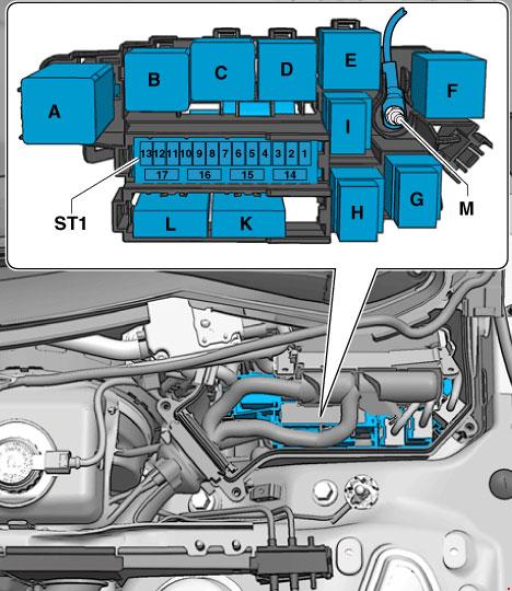
Protected components
- A. Used automatic glow plug system (until 2011)
- A. Power Relay for Engine Components
- B. Starter relay (up to 2011)
- B. Starter relay two
- C. Relay pump sec, air
- D. Ability relay cl. xxx (until 2011)
- D. Motronic Power Relay
- East. Fuel relay pump
- E. Relay add. fuel pump
- E. Coolant recirculation relay after engine shutdown
- E. Relay add. pump organization. cooling
- E. Gearbox cooling circuit relay
- East. Power relay for motor components 2
- F. non used
fuses for cars upward to Oct 2011 release
| 1 | xv A | Automatic transmission control unit of measurement. Mechatronic unit of measurement for dual clutch gearbox |
| 2 | five A | Engine oil level and temperature sensor |
| 3 | 5 A | Engine command unit. Air mass meter |
| 4 | 5a | Engine control unit of measurement |
| 5 | 10A, 15A, 20A | Air mass meter. Automated glow plug command unit. Secondary air pump relay. Low power heating relay. High power heating relay. Solenoid valve for boost pressure limitation. Crankcase ventilation heating resistor. Solenoid valve 1 of the adsorber. Secondary air control valve. solenoid valve for the left electro-hydraulic engine back up. solenoid valve for the right electro-hydraulic engine back up. The valve of the system of changing the geometry of the intake manifold. Air filter bypass flap valve -. Fuel pressure control. Fuel metering valve. Secondary air control valve 2-. Exhaust gas recirculation cooler changeover valve. Oil pressure relief valve. Fuel organisation diagnostic pump |
| half-dozen | 15 A | Engine control unit of measurement |
| 7 | 10A, 15A | actuator ane of the variable valve timing arrangement. actuator nine of the variable valve timing organization. Solenoid valve for heave pressure limitation. Solenoid valve 1 of the adsorber – the solenoid valve of the left electro-hydraulic engine back up. solenoid valve for the correct electro-hydraulic engine support. Valve i of the variable valve timing organization. Valve 2 of the variable valve timing arrangement. Charge air recirculation valve. Fuel pressure command-. Fuel metering valve. Intake manifold flap valve -N316-. Valve one of the exhaust camshaft adjuster -. Valve 2 of the exhaust camshaft adjuster. Climatronic coolant shut-off valve. Oil force per unit area relief valve. Fuel system diagnostic pump. Inflatable air cooling pump |
| 8 | 10A, 5A, 20A | Exhaust gas recirculation cooler pump -V400-. Ignition ringlet one with output phase. Ignition coil ii with output phase. Ignition curl 3 with output stage. Ignition curlicue 4 with output phase. Ignition roll 5 with output stage. Ignition curl 6 with output stage |
| 9 | 5A, 15A, 20A | Relay for additional fuel pump. Heating element for lambda probe 1 afterward catalytic converter. Heating chemical element for lambda probe 2 later on catalytic converter |
| x | 10A, 15A | Lambda probe heating element. Heating element for lambda probe 2. Heating element for lambda probe ane later catalytic converter |
| 11 | five A | Radiator fan command unit. Radiator fan control unit 2 |
| 12 | 5 A | Air mass meter. Automatic gearbox control unit of measurement mechatronic for dual-clutch gearbox |
from October 2011
| i | 15 A | Automatic gearbox control unit – mechatronic for dual clutch gearbox |
| 2 | v A | Engine oil level and temperature sensor |
| three | 5 A | Engine control unit of measurement |
| 4 | 5 A | Engine command unit |
| 5 | 10A, 5A | Air mass meter. Fuel pressure control. Fuel metering valve |
| 6 | xv A | Engine command unit – Injector 2 cylinders 1, 2, iii, 4 |
| 7 | actuator 1, 2, 3, four, five, 6, 7, 8 of the variable valve timing system. Solenoid valve for boost pressure limitation. Solenoid valve one of the adsorber solenoid valve of the left electro-hydraulic engine support. solenoid valve for the right electro-hydraulic engine support. Valve 1 of the variable valve timing organisation. Valve two of the variable valve timing system. Charge air recirculation valve. Fuel pressure control. | |
| 8 | 10A, 15A, 5A | NOx sensor ii. NOx sensor control unit of measurement 2 |
| 9 | 5 A | Voltage regulator. Engine control unit |
| ten | 10A, 15A | Lambda probe heating element |
| 11 | 5 A | Radiator fan control unit |
| 12 | 5 A | Automatic manual control unit |
| 13 | not used | |
| xiv | 5A, 20A | Engine Component Ability Relay 2. Ignition Coil 1 with Output Stage. |
| fifteen | 5 A | Power steering control unit of measurement |
| 16 | xv A | Thermostat for the parametric engine cooling organization. Automatic glow plug control unit of measurement |
| 17 | fifteen A | Lambda probe heater after catalytic converter |
Baggage compartment
Fuse box is located backside the right side trim. Item descriptions may differ from those shown.
Diagram

For cars up to 2010
| A | Sedan: Not used |
| B | – |
| C | Sedan: Heated rear window relay |
| D | – |
| Due east | Accessory Power Connector Relay |
| one | (30A) Torso lid control module |
| ii | – |
| 3 | (30A) Trunk lid control module |
| iv | (5A) Plug connector |
| v | – |
| 6 | – |
| 7 | – |
| 8 | – |
| 9 | – |
| 10 | – |
| 11 | – |
| 12 | – |
| 13 | (5A) Tire pressure monitor command module |
| 14 | (15A) Trailer control module |
| 15 | (20A) Trailer control module |
| 16 | (20A) Trailer control module |
| 17 | (5A) Electric parking brake command module |
| 18 | (15A) Suspension control module |
| 19 | (30A) Electric parking restriction command module |
| xx | (30A) condolement system |
| 21 | (35A) 4WD electronic control module |
| 22 | (30A) comfort organization |
| 23 | (20A) condolement system |
| 24 | (5A) vehicle location management organisation |
| 25 | (15A / 30A) Accessory ability connector |
| 26 | (15A) Heated seat command module |
| 27 | (7.5A) navigation system / radio |
| 28 | (30A) Audio system |
| 29 | (5A) Multifunction brandish command unit |
| thirty | (30A) Auxiliary heater control module |
| 31 | (30A) Electric parking brake control module |
| 32 | (30A) Heated seats |
| 33 | (30A) Door part command units |
| 34 | (5A) Auxiliary heater remote command receiver |
| 35 | (15A) Door function control units |
| 36 | (5A) Rear view camera control module |
| 37 | (15A) Accessory power connector |
| 38 | (15A) Accessory power connector |
| 39 | (15A) Accessory power connector |
| 40 | (15A) Cigar lighter |
| 41 | (5A) Self-parking control module |
| 42 | – |
| 43 | (5A) Distance control module (prowl command) |
| 44 | (15A) Rear window wiper motor |
| 45 | (5A) Electric parking brake control module |
| 46 | (5A) Lane modify assistance command unit |
| 47 | (5A) Heated seats |
| 48 | (5A) Hazard alarm lights, airbag control module |
| 49 | – |
| 50 | – |
| 51 | (10A/15A/25A) |
| 52 | (10AL5A) Special vehicle equipment |
| 53 | (5A / 15A) Automotive special equipment |
| 54 | (10A) Special vehicle equipment |
| 55 | (5A / 20A) Special vehicle equipment |
| 56 | (10A) Special vehicle equipment |
| 57 | (10A) Accessory power connector |
| 58 | (10A) Special vehicle equipment |
| 59 | (10A) Special vehicle equipment |
| 60 | – |
| 61 | (40A) Heated rear window |
from 2010
| i | not used | |
| ii | not used | |
| 3 | 15A. 25A | Warning system control unit |
| 4 | 15 A | Alarm system control unit |
| 5 | 5A, 15A | Special signal command panel, Alert system command unit of measurement |
| half dozen | Control panel for special signals. Alarm system control unit, Tachograph control unit. Male connector, 3-pin. Alarm memory | |
| 7 | 20 A | Control unit for special vehicles |
| eight | ten A | Alarm retentivity |
| 9 | 10 A | 12V socket |
| 10 | 10 A | Walkie talkie dividing relay, walkie talkie relay |
| 11 | 10 A | Walkie talkie dividing relay, walkie talkie relay |
| 12 | not used | |
| 13 | 30 A | Rear lid control unit two – |
| xiv | 15 A | Trailer detection control unit |
| 15 | 20 A | Trailer detection command unit |
| 16 | 20 A | Trailer detection command unit of measurement |
| 17 | 5 A | AUTO Concord button |
| eighteen | fifteen A | Command unit for electronic shock cushion adjustment |
| xix | 30 A | Electromechanical parking restriction command unit of measurement |
| 20 | 30 A | Convenience organisation central control unit of measurement |
| 21 | 35 A | All-wheel drive command unit |
| 22 | 30 A | Convenience system central control unit of measurement |
| 23 | 20 A | Convenience organisation central command unit |
| 24 | five A | Vehicle location system interface control unit of measurement |
| 25 | 30 A | Rear lid control unit |
| 26 | fifteen A | Correct front seat ventilation control unit |
| 27 | 40 A | Radio record recorder. Telephone transceiver – TV tuner. Mobile phone amplifier. Phone holder-. Male connector, 18-pin |
| 28 | 40 A | Voltage regulator |
| 29 | thirty A | Inverter with socket, 12V |
| 30 | 30 A | Boosted heater control unit of measurement |
| 31 | 30 A | Electromechanical parking brake control unit |
| 32 | 30 A | Switch with adjustable rear left heated seat. Heated Rear Right Seat Switch with Adjustment |
| 33 | 30 A | Correct doors |
| 34 | 5 A | Auxiliary heater receiver |
| 35 | 15 A | Right doors |
| 36 | 30 A | Additive dosing system control unit |
| 37 | 15 A | 12V socket |
| 38 | 15 A | 12V socket -. Inverter with socket, 12V – 230V |
| 39 | 15 A | 12V socket |
| xl | 15 A | Cigarette lighter |
| 41 | not used | |
| 42 | 5 A | Plug connector, 2-pin, in the backrest of the driver'southward seat. Plug connector, ii-pin, in the backrest of the driver'south seat |
| 43 | 7.v A | Park assist control unit |
| 44 | fifteen A | Rear window wiper motor |
| 45 | 5 A | Electromechanical parking restriction push |
| 46 | 5 A | Lane change assist command unit 2 |
| 47 | 5 A | Switch with adaptable rear left heated seat |
| 48 | five A | Trailer detection control unit of measurement. All-bike bulldoze control unit. Voltage regulator. Electromechanical parking restriction command unit |
| 49 | not used | |
| 50 | non used | |
| 51 | 20A, 30A | Digital audio system control unit. Radio cassette |
| 52 | 7.5A | Electronic data system control unit |
| 53 | 5A, seven.5A | Command unit for navigation system with CD drive. Radio tape recorder. Phone transceiver -. Idiot box tuner – Mobile phone amplifier. Telephone holder-. Male person connector, 18-pin |
| 54 | 5 A | Rear view photographic camera control unit |
| 55 | v A | Mobile Phone Amplifier |
| 56 | not used | |
| 57 | not used | |
| 58 | non used | |
| 59 | not used | |
| 60 | not used | |
| 61 | forty A | Heated rear window relay – Heated rear window |
The fuse number xl at 15A is responsible for the cigarette lighter.
Additional Information
In this video you tin can see the locations of the main presented relay and fuse boxes.
Also, Nosotros have posted a video on our YouTube aqueduct. Watch and subscribe.
DOWNLOAD HERE
02 Audi A4 Rev Lights Keyless Entry Windows and Sun Roof Not Working Fuse Is Good Free Updated
Posted by: collinsnoweepubt.blogspot.com
0 Response to "02 Audi A4 Rev Lights Keyless Entry Windows and Sun Roof Not Working Fuse Is Good Free Updated"
Post a Comment